This knowledge base offered by MiniTool company gives a general review of the popular CMOS inverter on digital integrated circuits or other electronic devices. Read it through and find the info you want.
About CMOS
CMOS, complementary metal-oxide-semiconductor, also called COS-MOS (complementary-symmetry metal-oxide-semiconductor), is a type of MOSFET (metal-oxide-semiconductor field-effect transistor). Its fabrication process makes use of complementary and symmetrical pairs of p-type and n-type MOSFETs for logic functions.
CMOS tech is used to construct integrated circuit (IC) chips like microprocessors, memory chips (including CMOS BIOS), microcontrollers, and other digital logic circuits. It is also used on analog circuits like image sensors (CMOS sensors), RF circuits (RF CMOS), data converters, as well as highly integrated transceivers for many types of communication.
What Is a CMOS Inverter?
First of all, let’s see what is an inverter. In digital logic, an inverter, also known as NOT gate, is a logic gate that implements logical negation. The truth principle of an inverter is that when you input “A”, it will output “NOT A”. For example, when you input “0”, the inverter outputs “1”; if you input “1”, it will output “0”.
Therefore, an inverter circuit outputs a voltage representing the opposite logic level to its input. Its primary function is to invert the input signal. That is to say, if the input is low, the output turns high and vice versa. This is also the working principle of CMOS inverter.
An inverter is able to be constructed with a single P-type metal-oxide-semiconductor (PMOS) or a single N-type metal-oxide-semiconductor (NMOS) and coupled with a resistor. The current flows the resistor in 1 of the 2 states, so the “resistive-drain” configuration is power-saving and fast.
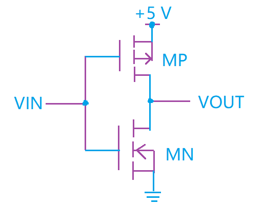
Alternatively, an inverter can be constructed by making use of 2 complementary transistors in a CMOS configuration, which is called a CMOS inverter. The advantages of CMOS inverter are very low power consumption and higher processing speed due to one of the transistors is always off in both logic states and the relatively low resistance (compared to the NMOS-only or PMOS-only type devices) respectively.
CMOS Inverter Layout
CMOS inverters can also be called NOSFET inverters. Within a CMOS inverter, there is a supply voltage VDD at the PMOS source terminal and ground connected at the NMOS source terminal. While WIN is connected to the gate terminals and VOUT is connected to the drain terminals.

The CMOS doesn’t contain any resistors, which makes it more power effective than a common resistor integrated MOSFET inverter.
How Does a CMOS Inverter Work?
Digital electronics circuits operate at fixed voltage levels corresponding to a logical 0 or 1 (binary). While a CMOS inverter circuit serves as the basic logic gate to swap between those 2 voltage levels. Implementation determines the actual voltage. Yet, common levels include (0, +5v) for transistor-transistor logic (TTL) circuits.
CMOS can also be constructed with bipolar junction transistors (BJT) in either a resistor-transistor logic (RTL) or TTL configuration.
Another meaning of TTL: Some Basics You Should Know about TTL (Time to Live)
CMOS Hex Inverter
The hex inverter is an integrated circuit containing six (Hexa-) inverters, such as 7404 TTL chip and 4049 CMOS. CMOS inverter 4049 IC has 16 pins: 12 pins are used by inputs and outputs, 2 pins are used for power/referencing, and the rest 2 pins are connected to nothing. The 7404 TTL chip has 14 pins.
An inverter is a basic building block in digital electronics. Multiplexers, state machines, decoders, as well as other sophisticated digital devices may use inverters.
Verdict
CMOS inverter is a vital component of a circuit device. it offers low power dissipation, fast transferring speed, and high buffer margins. Those three are designed qualities in inverters for most circuit design. That is why the CMOS inverter becomes popular.

